

CNC MACHINE.
Through a wide variety of CNC MACHINE
- service CNC MACHINE
Abstract:
This system is mainly based on two techniques, CNC machine and 3D printing. 2D plotter is used for drawing circuits on any surface like paper, cardboard as per the user requirement and conductive ink or marker is used as an object for drawing circuits. Conductive marker is placed in such a way that it can be moved in x and y direction using stepper motor and in up and down direction using servo motor. Arduino Uno or mega and CNC shield is used to drive motors. Benbox software is used to generate G-code and give input image of drawn circuit to the plotter. The research work is focused on a low cost and simple controlling system for 2D plotter machines to draw electronic circuit diagrams of PCBs on any surface.
I. INTRODUCTION
In last few years the production of electronic devices such as mobile phones, tablet, notebook, etc. has been increased tremendously. This technology revolution has been happened because of the large use of PCBs in every circuit. The operation of the electronic circuit is based on the flow of the electrical current through a desire paths from one point to another point. This path is drawn using the conductive marker placed on the 2D plotter.
There is also another method called photochemical method which uses ferric chloride compound to etch different layers of the board in order to clear the paths for the current, but in recent analysis it is found that the use of ferric chloride lead to significantly more risky for human health.
The implementation of this technique eliminates the human interaction with such compounds and replace the use of such hazardous chemical methods with a computerized mechanic system.
The working of 2D plotter is based on CNC machine and 3D printing where an object is moved with the help of two stepper motor in x and y direction as per the given input image. The input image is prepared with the help of express pcb or Autodesk eagle software. That image is converted into the numerical form of code known as g-code with the help of Benbox software which will give the instruction to the plotter to move the object from this point to that point in co-ordinates form as per layout. Here the object used is conductive marker as per our application.
II. SCHEME OF IMPLEMENTATION There are two systems implemented in this project.
A::
The first system is based on arduino UNO, BenBox software, Stepper motors, Servo motor and Conductive Marker.
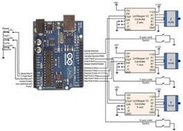
The second system is based on arduino MEGA, L293D shield, Inkscape Software, Processing software, DVD driver stepper motors, Servo motor and Conductive Marker. It is shown in Fig.2.
- Input supply
Input supply is of 12 V for both CNC shield and L293D motor shield, which is used to drive motors and 5v supply is given to the arduino board.
- Arduino IDE
It is a software that gives software development tools for Arduino development boards. In this project we have to interface motors and check for serial communication using arduino IDE.
Arduino uno or mega platform is used in this systems which drives the motor with the help of CNC shid and L293D motor shield. The g-code instructions are given from the Benbox and processing software. Arduino UNO has Atmega328p and Mega has ATMEGA 2560 microcontroller. Technical features are shown in table.1 below.
- Please confirm that I have understood the task correctly. You would like me to rewrite the given text to make it clearer by correcting any spelling, grammar, and punctuation errors and improving its overall clarity and readability. Is that correct? Arduino IDE, Express PCB or Autodesk Eagle, Benbox.Autodesk Eagle is a software that is used to design the board layout of any circuit. An example of a
- 5V 1A power supply circuit.
- The G-code of an image is generated using Benbox software. It is only supported by the Windows operating system. It can configure the microcontroller. Speed, steps, and other parameters can be controlled using this software. The output from Autodesk Eagle which is a mirror image of the layout when imported uses its own default algorithm to find out the coordinates and generates a hex file.

G-code is the numeric code which tells the machine to go from a one position to the other specific position.
- Hardware used in this system: Components required to build this system are CNC shield, Arduino UNO, A4988 motor driver, DVD drive stepper motor and MG90s Servo motor.
Setup between Arduino UNO, motor driver and stepper motor

- A4988 motor driver is used to drive one stepper motor. It is placed on the CNC shield. It can operate on 5 to 36V supply voltage and upto 2A current.

It is a 16 pin Ic. Input is given to the STEP and DIR pin of the IC and output is taken from 1a, 1b, 2a &
2b for motor. Driver and its connections are shown in the Fig
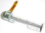
- The motors used in this setup are stepper motors and are taken from the DVD drives. Two motors are required, one for x direction and other for y direction. the input supply given to this motor is 12V, given through a shield. The step angle is 18 degrees. Its holding torque is 25g.cm.[5]. The motor used is shown in the Fig.9.
- MG90s Servo motor is used for the movement in z direction that is for up and down movement of the conductive marker. It requires 5V supply voltage. It has 180 degrees step angle. Torque is 1.8kgf.cm..

Hardware setup of 2D plotter using Arduino UNO

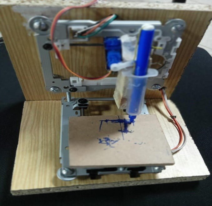
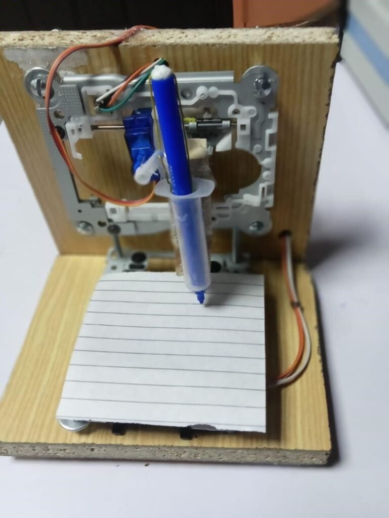
The system developed can draw a circuit using a conductive marker, which is a g-code of the image given to the Arduino Mega using processing software.
IV. CONCLUSION
This project can play a vital role in the Research and Development field, where we can print an idea of any circuit that comes to mind on paper or cardboard using conductive ink and check the different components working with the same circuit in a short period of time.
The main aim of this project is to reduce the bulkiness of PCB, which gives rise to the new technology of flexible electronics by enabling the printing of the circuits on surfaces like cardboard and photo papers. G-code is used to plot the location easily. The design of this project is to reduce error and increase accuracy & productivity. This project is helpful for students during their implementation of the project as far as cost and time are concerned.
The first system, which was based on Arduino UNO and CNC shield, was unable to draw images directly given in the g code form. It only draws the diagrams which are drawn in the Ben Box software. Thus, we go for another system, which is based on Arduino MEGA and L293D shield, which can draw any image given to the system in the form of g code.